There were times when I just didn’t think of taking pictures of some phases of the project or just down
right forgot to. The following are things done and or changed .
Front shocks > used Ford style with the stud on top and KYB brand, cut back the OEM top shock mount on
the upper control arm as the design really didn’t "shock" all that well. I’ll hand it to Plymouth for getting
the jump on the IFS but not on the shock setup. Now I cut the top mount back as far to the "A" arm as I could , in order to
clear the wheels in full steer I had to make mounts that I welded on the frame rail, they looked like the old VW bug setup,
sort of. I had tried different shocks and the best ride was given by KYB. With the front lowered some I have about 2 3/4"
travel up and down, and it doesn’t bottom out unless I guess I take a ride on the NY BQE.
The master cylinder and proportioning valve is that of a one ton and up GM, the hydro boost for the
power brakes is the same, with an new "not rebuilt" master cylinder and making hoses and all the brake lines took some time.
(Hint) save your self a lot of headaches and get your rear gas and brake lines in while the body is off the frame, also the
wire harness for the fuel gauge, elec. Fuel pump" if your not using the OEM manual one" and rear lights, etc. On this project
all the parking brake cables are that of early 67-68 camaro/firebird right up the OEM handle under the dash. It’s wise
to get all the things you can get mounted before you put the body back on.
The gas tank ... again we used 67 camaro/firebird , it was the closest I could find to the OEM size and gallon
capacity . Just had to make new mounting and straps since we had nothing but rusted unuseable junk. The filler on the tank
for the model year of 67 was in the center rear of the tank as the licence plate hid the fill bung and cap. With a saws-all
I carefully cut the bung about a 1/4"+ from where it entered the tank. Then took and cleaned it up free of dirt and oil/s
as I was going to solder a freeze out plug in the hole . After that was done the next move was to make the mounting straps
and set the tank in the car to figure where the new bunge ( filler tube/pipe) was to be located , after figuring that out
I went and got a 45 and a 90 degree exhaust pipe/s and alined everything to mate to the hole in the left rear fender where
the OEM filler/bunge was. It work out just fine after soldering it all up and testing it I was going to give it a shot of
Por-15 and then some bed liner paint to deaden sound and protect it form the elements . After that the next day I installed
the sending unit and mounted the tank. " I always had a habit of tweaking the float " to where there is about 5 + gallons
when your on a quarter tank or just under that mark.. I never ran out of gas and don’t intend to, this will assure
it never happens .
The tilt wheel and steering, the tilt wheel came out of a mid to late 80's S-10 with out cruise control .
The fit to the car’s fire wall and bottom mount of the dash was as close as anyone could want it. However, there were
a few modifications that needed to be addressed. I think the column measured up well for either a steering box or a R&P
. I kept the telescoping end to be used with this project , it needed a good cleaning and some lube in order to have it do
what it was designed for. The rack I used was a late model GM if I recall 2003 was the year. I purchased a rebuild form my
local auto parts dealer in have been using for over 23 years, the price was right and they let me take one of everything off
the shelf to see what one I figured I could make fit . "the same thing was done to find a hat rotor to fit the OEM spindles"
ya got to love a place like Hapi Auto. Anyway after we selected and elected a R&P the next thing was to get the
rest of the hardware from the local bone yard, since I needed a core and that cost was more than the rebuilt rack it was wise
to get everything from the steering column to the tie rod ends at the bone yard. After looking around to find a good doner
car we then had them remove all the parts we needed. I did this to make sure I wasn’t getting parts from a car that
was hit in the front since I need the tir rod ends and tire rods, rack mounts and the bolts that go into the rack are not
a easy item to locate. How do I know that...ask me or call a GM dealer. The best route was a everything deal at the bone yard.
"Cost effective, hand picked good used parts".
I made my own mounts for the rack, it was easy and in order to get clearance to fit under and around everything it was
the only to fly. Although it was a tad tricky to make sure that the Hyd. Hoses would be able to changed easily and
fit correctly and the alinement with the steering column and to be on the money. A got to take time in every area of the build
where safety is a concern and set it up to where you can remove things without taking half the car apart . I can remove with
no problem/s : the headers & exhaust system, r&p, steering column , elec cooling fan and radiator , water pump comes
right out when they are out, I could get the WP out and leave the rad. In but that would only be done it it were a field repair.
That’s the way I like it and wanted it .
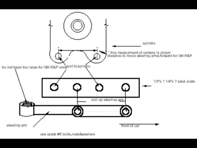
The next problem was the 1939 OEM steering arms, they were too long and the tie rod taper hole was too big
. No other thing to do but make it work and that we did with the use of our 3-in-1 lathe . I just purchased this machine in
May of 2004, just a few months before the coupe project and I’ll say with in a year it has paid for it’s self
and then some ... I think I covered the method I used to get the steering arms correct in the page with the photos . One day
I’ll take a picture of what it looks like and post it. It’s easer that way than to explain the procedure. for
now ...Here’s a sketch at the bottom of this page with the procedure I came up with .
The wiring in this project car was home made with a stock fuse box from a 79 pick up truck. It wasn’t all that hard
to do and the price was just right. Our rear lights, front parking and directional/s are LED, along with the third break light
I made . All indicator lights on the dash are also LED’s "it’s the only way to go , less voltage and longer life.
I wired up the coupe more or less like a VW since I always admired the way the system worked , shut the engine off and
everything goes off but the hazard (4 way) lights. The battery is in it’s stock location under the drivers side seat,
I had to install an additional battery in the car as to aid in the use of the sound system that was installed , with the 1000
watt amp it was a must when we are not driving to listen to some CD’s and not drain down the primary battery. Remember
that you can never have enough of ground cables and or wires to your dash, engine , body and frame, more electrical problems
boil down to a bad ground from what I have seen on the things I work on. any wires passing through sheet metal must have a
good grade rubber grommet and all the harness should be fastened securely, you don’t want to have a short on the way
to the show or cruise and ruin your day so take the time and double check everything twice.
The sealed beam head lights: we couldn’t find any OEM headlight pots as I stated in the page that mentions this issue,
so I made a set up and mounted them in the fenders as they are much brighter than the OEM system. And since the 39 was the
only year for the semi square head lights I wanted to retain that feature that came in that year. A lot of work but well worth
it. The directional’s got wired up just like the S-10 that the steering column came out of, it isn’t all that
hard to do and it beats a universal switch by a mile . And having the high beam switch on the column is another plus "But
it tough to get my foot up to the steering wheel to the switch?" . I had though of changing out the S-10 steering wheel but
it’s design and feel works great with the lay out of the gauges, so it stays there .
The exhaust system on out project was also home made. I ordered a pair of 56"x4"OD 16ga. Triple chrome pipes from flexatube
,they had the gauge I was looking for, a bit heavier than the normal flash chrome pipes everyone else sells but the price
was good . Off the Dyno Max block hugger headers from the collectors with two 90 degree mandrel pipes on each side everything
lined up better than I expected .I had to make some reducers from stainless steel along with baffles of the same material.
This was a first for me to make a set of side pipes like this from scratch, I’m use to the old circle track days with
4" off the collectors and it crossed my mine but I knew if I went that route I would run into problems come inspection time
and on the road . I welded two tabs to each pie after blocking them up where I wanted them and making templets for the bottom
of the frame rails, then I made some rubber insulators to mount the pipes to the frame, they helped in causing vibration
form the motor . The material used for the baffles was SS with 1/8" holes 26" long with two sections capped and packed 8"
long on each end . The overall sound is nice, it sounds like a big Harley . I would estimate that these pipes would last a
lot longer than the light weight ones I have seen and they wont rust all that soon due to the triple chrome plating. Everything
cost a tad over 286.00 bux’s from the collectors back, not a bad a t all and they look great, they are tucked under
the rocker panels and don’t stick out past the rockers where you get in or out with the door open .
The glass in this project is all new "gray smoked" except for the windshield,since we did have all the original glass and
although it wasn’t cracked or foggy looking I wanted to get new glass cut just because . All the window gaskets came
form "Steel Rubber"I was shopping around and they had the price and quality product I was looking for . For all the items
I did order for the car the gas fill bung rubber grommet really doesn’t fit the arch of the 39 Plymouth fender all that
well, but what can you do when your ready to go on the road...use it ! I have seen others with the same complaint on this
item so I’m not alone .
We had the glass cut at Bart’s Glass in Bound Brook NJ, 25 + years ago I had him do the 37 4ord I built and liked
his work and price. The rear diff. Is that of a 67-70 Camaro posi /drum brakes( freeB). The fit was quite easy , I just blew
off the OEM spring perches with the plasma cutter, cleaned them up and tack welded them to the width of the OEM rear diff.,
since the springs appeared to be good but it would sit a bit higher then I wanted, we set everything in and up along with
the pinion angle. Everything in this phase has got to be given the once over three times before you weld it in solid . You
have to measure, measure, measure . You don’t want the car to go down the road where it looks like a dog running, if
you get what I’m saying . Later down the road as we got about 300 miles on the car the rear springs settled down some
so now I had to take out the lowering blocks I made that I for got to mention before, it wasn’t a difficult job at all
but now I’ll change shocks since the ones I had on are too long now, the change was to a good gas shock and now the
car sits the way I want it and rides a lot morebetter. "Like that word".